Difference between revisions of "Assembly drawings"
| (3 intermediate revisions by the same user not shown) | |||
| Line 27: | Line 27: | ||
'''Creating Build Strategy Drawings''' | '''Creating Build Strategy Drawings''' | ||
| − | *1.Select ShipConstructor / Navigator | + | *1.Select '''ShipConstructor / Navigator'''. |
| − | *2.Click the Build Strategy page in the component list. | + | *2.Click the '''Build Strategy''' page in the component list. |
[[Image:file1.jpg]] | [[Image:file1.jpg]] | ||
| − | *3. Click New. | + | *3. Click '''New'''. |
*4.Select the drawings that you want to include then click OK. | *4.Select the drawings that you want to include then click OK. | ||
| − | *5. The following dialog then asks for the file name of the new build strategy drawing. Enter a name then click OK. | + | *5. The following dialog then asks for the file name of the new build strategy drawing. Enter a name then click '''OK'''. |
[[Image:file2.jpg]] | [[Image:file2.jpg]] | ||
| Line 64: | Line 64: | ||
Assembly levels have been explained at the beginning of this chapter. This button displays the dialog that allows you to customize the assembly levels to suit your particular job and manufacturing process. | Assembly levels have been explained at the beginning of this chapter. This button displays the dialog that allows you to customize the assembly levels to suit your particular job and manufacturing process. | ||
| − | *1. In the Build Strategy dialog click Levels. | + | *1. In the Build Strategy dialog click '''Levels'''. |
[[Image:file5.jpg]] | [[Image:file5.jpg]] | ||
| Line 72: | Line 72: | ||
[[Image:file6.jpg]] | [[Image:file6.jpg]] | ||
| − | *3. Click Add. | + | *3. Click '''Add'''. |
[[Image:file7.jpg]] | [[Image:file7.jpg]] | ||
| Line 78: | Line 78: | ||
*4. A new level is created. Enter a name for the new level. If you make a mistake on where the level is in the order you can click the Move Up or Move Down buttons to move the selected level. | *4. A new level is created. Enter a name for the new level. If you make a mistake on where the level is in the order you can click the Move Up or Move Down buttons to move the selected level. | ||
| − | *5. Click OK to update the levels to the database. | + | *5. Click '''OK''' to update the levels to the database. |
| Line 84: | Line 84: | ||
| − | Permissions: Build Strategy / Edit | + | ''Permissions: Build Strategy / Edit'' |
'''Adding Assemblies to the Build Strategy''' | '''Adding Assemblies to the Build Strategy''' | ||
| Line 94: | Line 94: | ||
[[Image:file8.jpg]] | [[Image:file8.jpg]] | ||
| − | *3. The right click menu appears. Select New Assembly. The following dialog is displayed. | + | *3. The right click menu appears. Select '''New Assembly'''. The following dialog is displayed. |
[[Image:file9.jpg]] | [[Image:file9.jpg]] | ||
| Line 103: | Line 103: | ||
''' Move Parts to the Assembly''' | ''' Move Parts to the Assembly''' | ||
| − | + | *Select the parts you want to move. You can multi-select by using the Shift and Ctrl keys. You can now drag and drop the parts to an assembly. | |
'''Dragging and Dropping''' | '''Dragging and Dropping''' | ||
| Line 109: | Line 109: | ||
[[Image:file10.jpg]] | [[Image:file10.jpg]] | ||
| − | |||
| − | |||
| − | |||
| − | |||
| − | |||
'''Selecting''' | '''Selecting''' | ||
| Line 132: | Line 127: | ||
*1. In the Build Strategy dialog use the light bulbs to make the parts you want to assign visible. | *1. In the Build Strategy dialog use the light bulbs to make the parts you want to assign visible. | ||
| − | *2. Click the Assign To Assemblies button. | + | *2. Click the '''Assign To Assemblies''' button. |
**Select Objects: | **Select Objects: | ||
| − | *3. In the main drawing window select the parts you want to assign to a different assembly, then press ENTER. | + | *3. In the main drawing window select the parts you want to assign to a different assembly, then press '''ENTER'''. |
[[Image:file11.jpg]] | [[Image:file11.jpg]] | ||
| Line 142: | Line 137: | ||
*4. The Assign Parts to Assembly dialog is displayed. | *4. The Assign Parts to Assembly dialog is displayed. | ||
| − | *5. Select the assembly you want to assign to and click OK. | + | *5. Select the assembly you want to assign to and click '''OK'''. |
'''Manager Settings for Assembly''' | '''Manager Settings for Assembly''' | ||
| − | *1. BOM Manager | + | *1. '''BOM Manager''' |
[[Image:file26.jpg]] | [[Image:file26.jpg]] | ||
| − | *2.Assembly Drawing | + | *2.'''Assembly Drawing''' |
[[Image:file16.jpg]] | [[Image:file16.jpg]] | ||
| − | + | '''Assembly Create''' | |
| − | *1. Select ShipConstructor / Navigator | + | *1. Select '''ShipConstructor / Navigator'''. |
| − | *2. Select the Assembly page in the component list. | + | *2. Select the '''Assembly''' page in the component list. |
| − | *3. Click Create. | + | *3. Click '''Create'''. |
[[Image:file18.jpg]] | [[Image:file18.jpg]] | ||
| Line 175: | Line 170: | ||
[[Image:file15.jpg]] | [[Image:file15.jpg]] | ||
| − | *5. Click OK. | + | *5. Click '''OK'''. |
*6. The Following dialog will appear. This allows you to select a template drawing and BOM for the drawings that will be generated or use the ones assigned in Manager. | *6. The Following dialog will appear. This allows you to select a template drawing and BOM for the drawings that will be generated or use the ones assigned in Manager. | ||
| Line 181: | Line 176: | ||
[[Image:file19.jpg]] | [[Image:file19.jpg]] | ||
| − | *7. Click Next. | + | *7. Click '''Next'''. |
*8. In the next dialog check the box in front of assemblies that you want to create drawings for. | *8. In the next dialog check the box in front of assemblies that you want to create drawings for. | ||
| Line 191: | Line 186: | ||
*10. Check the checkbox next to PANEL in the Include Levels list. | *10. Check the checkbox next to PANEL in the Include Levels list. | ||
| − | *11. Click Set. | + | *11. Click '''Set'''. |
| − | *12. Click Finish to create the assembly drawings. | + | *12. Click '''Finish''' to create the assembly drawings. |
| − | + | '''Smart Labels''' | |
''SC Assembly/ Annotation/Create'' | ''SC Assembly/ Annotation/Create'' | ||
| Line 215: | Line 210: | ||
[[Image:file21.jpg]] | [[Image:file21.jpg]] | ||
| − | + | '''Icons - Orientation''' | |
| − | + | ''SC Assembly/Icons/Orientation'' | |
[[Image:file23.jpg]] | [[Image:file23.jpg]] | ||
Latest revision as of 10:47, 13 January 2010
Terminology People in different areas or industries have different understanding about the meaning of specific words when it comes to build strategies or assemblies.
PWBS (Product Work Breakdown Structure)- A structural system describing the logical sequence in which parts are put together to form a project. This can also be used in exchange with the term Build Strategy. Build Strategy often has times of execution associated with a specific structural stage.
PROJECT Level - Is the top level within a project. It can only contain one item, which has the name of the project. ShipConstructor creates this level and the project item automatically when starting a new project.
UNIT Level - ShipConstructor works in UNITS when it comes to structural modeling. You register a UNIT and work on one unit at a time. This level is predefined when starting a new project. Every project has to have at least one UNIT. The UNIT items are automatically created when you add a UNIT to a project.
PIPE SPOOL Level - ShipConstructor automatically generates this level. This level is reserved for pipe spools. Pipe spools can be assigned to any other sub-assembly.
HVAC SPOOL Level - ShipConstructor automatically generates this level. This level is reserved for HVAC spools. HVAC spools can be assigned to any other sub-assembly.
Most common production process uses assembly levels similar to these four:
PROJECT - Top most level.
UNIT - Several units within a ship or offshore structure. A small project could consist of only one unit (hull plus wheel house) or many units.
3DASSEMBLY - Often just called ASSEMBLY. In general 3DASSEMBLIES are put together from several panels plus individual parts. Within a unit one would typically have assemblies like the double bottom, a wing tank or similar.
PANEL - Panels may be flat or curved and traditionally consist of one of more plate parts plus several stiffeners.
Feel free to add more assembly levels to the project if you need them. Often the final assembly is carried out using many STAGES that usually combine 3DASSEMBLIES and PANELS. In some cases there are as many as 20 STAGES between the 3DASSEMBLY and the UNIT.
Creating Build Strategy Drawings
- 1.Select ShipConstructor / Navigator.
- 2.Click the Build Strategy page in the component list.
- 3. Click New.
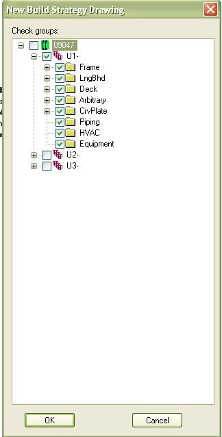
- 4.Select the drawings that you want to include then click OK.
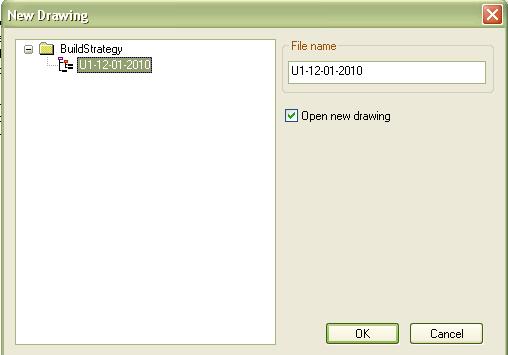
- 5. The following dialog then asks for the file name of the new build strategy drawing. Enter a name then click OK.
- 6. Decide whether you want Production information as well as the solids to be displayed. This applies only to structural and equipment parts. Both of these part types consist of the production layer information, for example the cutting path for plate solids, and solid information. In most cases, it is sufficient to use only the solids. Click No.
- 7. The build strategy drawing is created. Now you can change you viewpoint and run the next command.
Develop Build Strategy
- 1. Create a build strategy drawing (if necessary). If you open an old build strategy drawing, any parts that have been created after the drawing was made (or updated) will not show up.
- 2. Set up a 3D view point that suits your needs.
Creating Levels
Permissions: Build Strategy / Edit Levels
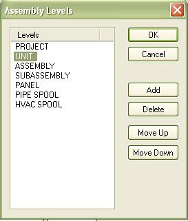
Assembly levels have been explained at the beginning of this chapter. This button displays the dialog that allows you to customize the assembly levels to suit your particular job and manufacturing process.
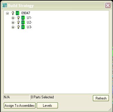
- 1. In the Build Strategy dialog click Levels.
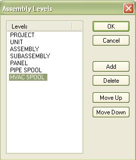
- 2. Select the level above the one you want to create.
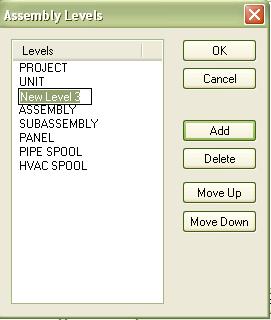
- 3. Click Add.
- 4. A new level is created. Enter a name for the new level. If you make a mistake on where the level is in the order you can click the Move Up or Move Down buttons to move the selected level.
- 5. Click OK to update the levels to the database.
Setting up the Build Sequence
Permissions: Build Strategy / Edit
Adding Assemblies to the Build Strategy
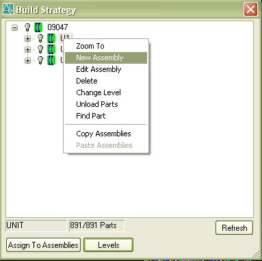
- 1. In the tree, select the assembly that you want to add a sub assembly to.
- 2. Right Click.
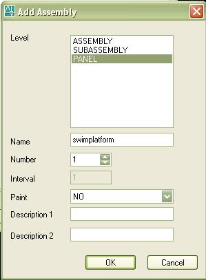
- 3. The right click menu appears. Select New Assembly. The following dialog is displayed.
- 4. Fill in the data in the dialog and click OK.
Move Parts to the Assembly
- Select the parts you want to move. You can multi-select by using the Shift and Ctrl keys. You can now drag and drop the parts to an assembly.
Dragging and Dropping Left click and hold down the mouse button on the selected parts then drag the mouse until the cursor is over the assembly you want to assign the parts to then release the left mouse button. You can also move assemblies only if the level of the assembly you are moving is below the level of the one you are moving it to.
Selecting
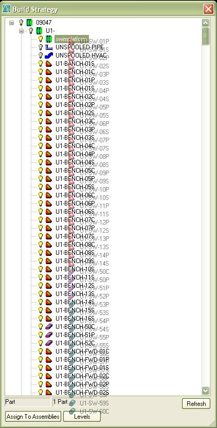
The build strategy tree is a modeless dialog. This means you can work in the dialog and in the drawing without closing the dialog. This lets you use AutoCAD in the background. This is helpful for selecting parts in the tree.
· Pick parts in the drawing and their respective names will be selected in the Build Strategy tree.
· Select parts within the tree and the parts will be highlighted in the drawing.
Note: You can use other functions while the build strategy control is running, such as the orbit command to change your viewpoint, or you can change to a shaded or hidden mode.
IMPORTANT: You cannot UNDO a build strategy assignment.
Assign To Assemblies
This is another way to assign only parts to assemblies. You cannot assign assemblies to other assemblies. This function has been kept, since many users have been accustomed to it.
- 1. In the Build Strategy dialog use the light bulbs to make the parts you want to assign visible.
- 2. Click the Assign To Assemblies button.
- Select Objects:
- 3. In the main drawing window select the parts you want to assign to a different assembly, then press ENTER.
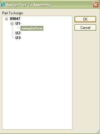
- 4. The Assign Parts to Assembly dialog is displayed.
- 5. Select the assembly you want to assign to and click OK.
Manager Settings for Assembly
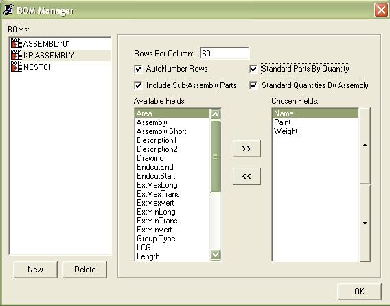
- 1. BOM Manager
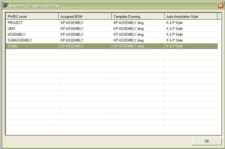
- 2.Assembly Drawing
Assembly Create
- 1. Select ShipConstructor / Navigator.
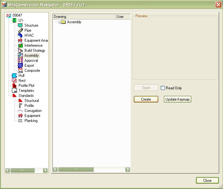
- 2. Select the Assembly page in the component list.
- 3. Click Create.
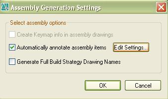
- 4. Two options are available for assembly drawings:
- 5. Click OK.
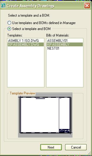
- 6. The Following dialog will appear. This allows you to select a template drawing and BOM for the drawings that will be generated or use the ones assigned in Manager.
- 7. Click Next.
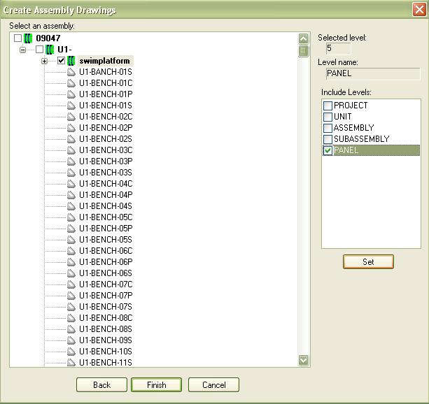
- 8. In the next dialog check the box in front of assemblies that you want to create drawings for.
- 9. Check the checkbox next to the unit in the tree.
- 10. Check the checkbox next to PANEL in the Include Levels list.
- 11. Click Set.
- 12. Click Finish to create the assembly drawings.
Smart Labels
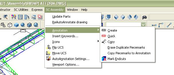
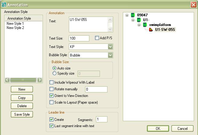
SC Assembly/ Annotation/Create
- 1. Start the command.
- 2. Click the part to annotate.
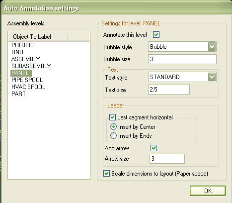
- 3. Select the options from the dialog as explained below.
- 4. Click OK.
- 5. Pick the locations and direction for the leader line(s) and the piecemark.
- 6. Repeat for all other parts.
Icons - Orientation
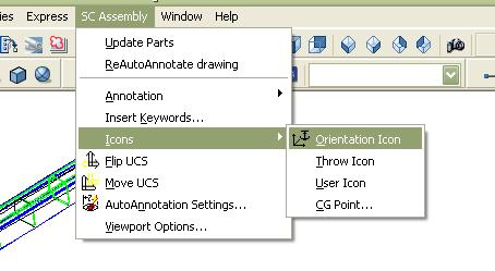
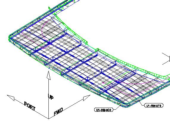
SC Assembly/Icons/Orientation
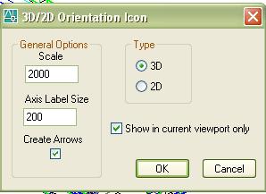
- Inserts an orientation icon into the drawing.
- 1. Start the function.
- 2. Select the type of icon you want. The Scale is the length of the direction arrows. Click OK.
- 3. Pick a location for the icon.
