General applicable rules
GENERAL APPLICABLE RULES when using SC2005 & SC2008
Rules for viewing the structure:
- Frames - always look from AFT to FORWARD. The structure in FWD is marked dashed.
- Longitudinals- always look form STARBOARD to PORTSIDE. The structure in PORT is marked dashed.
- Decks- always look from TOP to DOwn.The structure under deck is marked dashed.
In every project you have to search for the sign where the thickness of frames is changing form Aft to Forward.
Structure part colors
- Green - outside cut
- Yellow - inside cut
- Cyan - continuous or dached - marking line
- Grey - no process (only text is part of plate parts).The other Grey entities except parts must be on CON layer.
PLANAR GROUPS
The start of every project is creating planar groups using Rhino sections for frames, longitudinals and decks.
In every planar group after creation must be done the following:
- SC Utilities/Remove vertices below tolerance: 0.05
- SC Utilities/Activate UCS. SC2005 is planar gr name _C (ex. U1-F00_C) in SC2008 is planar group name_M.(ex. U1-F00_M)
- SC Utilities/3D to 2D
- Add the base lines/Central line using tool palette and customize it for the project.
PIECEMARK
In a Shipconstructor project first we define the plate parts and than the profiles if required. The piecemark has the following sizes:
- 40 for plate parts
- 25 with leader for profiles.
Function of the plate part size we dicrease the piecemark size with 5 every time till it will fit inside the part.
If you need to delete a defined part (a block with piecemark which is added to the project database) than DO NOT USE DELETE but UNDEFINE which is a ShipConstrutor tool. If you need to modify a defined part than you can choose for one of methods below:
- Undefine the part with keeping the autocad entities and than define it again. Is used when you need to modify the solid also.
- Deactivate the part, modify it and reactivate it again. Is used when you do not need to modify the solid.
PLANAR GROUPS
- Look for watertight bulkheads and tank plates, these are without scallops.
- Start drawing the continueing construction. This means the parts of the construction which continue when passing other planar groups. Finish the planar group completely with profile solids (even if they are not in the scope of delivery). The reason is that you can use the intersections in the not-continueing planar groups.
- When creating a new planar group take use the correct thickness and thickness throw. This is imortant for marking group intersections. When you finish a planar group, check the 3D model with the intersecting/connecting planar groups for possible irregularities.
- When a planar group is intersected with a skewed group, then make the skewed group first to have the correct intersection markings.
- Connecting construction fully detailed in no process for all frames and centerline, linetype continuous for near side, dashed for far side
- Draw connecting sections to show how construction continues
- Replicate
PARTS
- For every import remove vertices below 0.05mm
- Close outside and inside contours
- Split part if it is bigger than the sheet size, conform the following rules:
- Shortest welding line
- Parallel to a reference line, at intervals of 50mm
- Minimum 50mm distance to adjacent construction
- Show reference lines, every part has to have at least 1 reference line
- Mark all interfering construction (plates, stiffeners)
- Show thickness
- All marking lines and No process entities to be within part borders
- If applicable show:
- Orientation icon
- Contra templates’
- Group together:
- Piecemark
- (Orientation icon)
- (‘Contra templates’)
- Text and piecemarks which do not fit within the part borders to be incremental decreased with 5
- Inside cut:
- Holes smaller than Ø50 are marked instead of cut
- Cuts <6mm to be marked (palsma cut is 6mm minimum)
- No process:
- text only
- Not to interfere with markinglines
- Bending parts:
- Maximum bending length is 4000mm (machine limiet)
- Bending requires at least 50mm plate next to the bending line, if the bending stops at the plate edge, add 50mm stock
- Always mark the plate at the side where the bending goes to (this side), ‘other side’ only to be used for exceptions
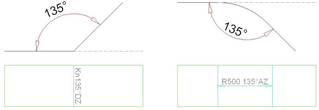
- Flange: indicate with bending line and diamonds, text example: FL50 90°TS
- Knuckle: indicate bending line, text example: KN 45°TS
- Radius: Indicate begin and end of bending with a line
- Draw an arrow from begin line to end line and inidicate:
- Knuckle/Radius
- Angle
- Bending direction ‘this side’ (‘TS’ or in Dutch ‘DZ’) or ‘other side’ (‘OS’ or in Dutch ‘AZ’)
- When creating the part select ‘Bending’ in the Paint menu.
- Radius: Indicate begin and end of bending with a line
- Welding bevel:
- when indicated on the plate, it is done for all sides
- Indicate:
- bevel in degrees or ‘NO BEVEL’ for 0 degrees
- side ‘this side’ (‘TS’ or in Dutch ‘DZ’) or ‘other side’ (‘OS’ or in Dutch ‘AZ’)
- example ‘BEVEL 30 TS’
- Stock is indicated with a + and the amount example ‘+50’
- Long narrow parts with curvature – mark straight sightline
- Sightlines
- Add to long narrow parts which migh deform during construction(build T-profiles, etc.)
STANDARD PARTS
- For every part appearing ≥5 times.
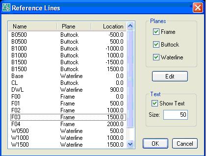
REFERENCE LINES
- Origins are centerline and baseline.
- Spacing is standard 500mm
- F frame 2 digits
- B buttock 4 digits
- W waterline 4 digits
- Layers/colors:
- Lines _PRD marking
- Text _PRD no process
- Text height 50
MARKING LINES
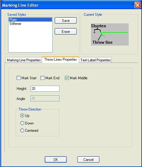
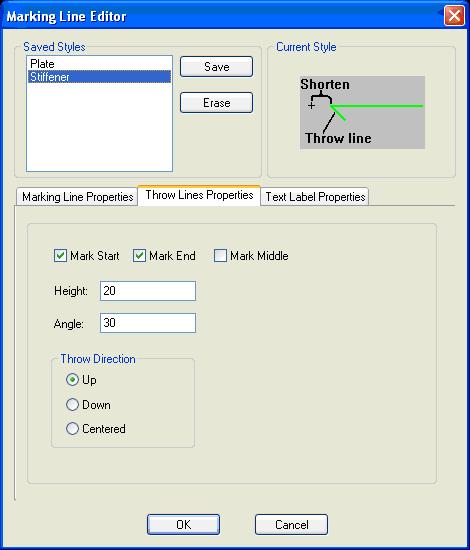
- Plates are marked with a marking line at the CL and a double bubble
- Profiles are marked with a marking line at the CL and end markings at both ends
- Continuous line when on near side, dashed when on far side
- Holes are marked as the following:
- < Ø20 marked with cross
- Ø 20-50 marked contour + cross
- > Ø50 inside contour (cut)
ORIENTATION ICON
- In every curved plate
- In every part which is hard to identify from it’s shape
- Use only:
- FWD forward
- UP up
- CL centerline
CHECK
General
- Layer use:
- _PRD Part contours, marking lines and no process entities
- _SLD Part solids
- _REV Back up of surfacemodel sections, stringer cutouts
- _CON All entities which must appear in the printed drawing but not on parts (no Shipconstructor entities)
- Vertices removed (0.05mm)
- Textstyle and height
- Linetype scale (dwg must be scale 50)
- Purge
Building kit plate
- Check solids for interference with intersecting/connecting structure
- Fame + CL girder:
- Baseline (+ centerline for frames)
- Title
- Fully detailed intersecting structure in 'no process'
- Scallops for welding connecting structure
- Scallops for shell seams
- Limberholes
- Stringer cutouts in T section – add bridge if cutout is deeper than half web height
- Presence of sightline on long, narrow curved parts
- Watertight bulkheads
- No scallops
- No stringer cutouts
- Tank
- Breather/bleederholes
- No scallops in tankwalls
- Additional limberholes where required
- Reference lines:
- Every part at least 1 reference line (intermediar if necessary, except at small brackets)
- Marking lines on reference lines to be ignored
- Marking lines
- For all connecting structure
- Correct line type (continuous/dashed)
- Bubble for plate
- Double arrow for stiffener
- No process lines – correct line type (continuous/dashed)
- No lines to extend beyond part contour
- Plate thickness on every part
- Text not to interfere with other entities
- Curved plate:
- Mark all connecting construction
- Framelines to have bubble for thickness throw indication
- Presence of correct orientation icon
Building kit plate + profile
- Type and length for every profile
- Stiffener endcut indication
- Stiffener start- and end symbols
Construction detail drawing
- Shell seam symbols
- Stiffener end cut symbol
- Centerline or baseline for every planar group


