SC Hull
Contents
[hide]Surfaces and expansions
How to position in the drawing
Templates
Templates are required for plates which need mechanical processing (bending or forming) to obtain the desired shape.
We need templates in the following situations:
- Single curvature (bending) with constant radius - no template required, give bending info on plate.
- Single curvature (bending) without constant radius - 1 template required.
- Double curvature (forming) - minimum 3 templates required.
Template types
- Bow Fashion - for plates which are on the center line and have symmetry around the center line (for example a bow cone)
- Standard - all other plates:
- Create the templates on the reference lines, as perpendicular to the surface as possible, or if this is not applicable:
- Use Auto-Level
Template label
- Plate Name
- Marking Line Name
- Bracket Angle
Template name is plate name + reference line name or, when using Auto-Level, plate name + T1 (T2, T3, etc.)
Template style is Plate
Edge margin 50mm
Check list SC HULL
- Expansion settings
- General
- Expansion Option Find Best Strain Fit
- Stretch Expanded Plate None
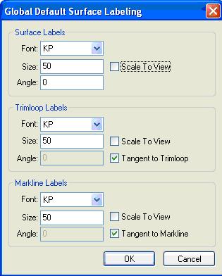
- Text size 50
- Roll Lines None
- Add Stock
- None
- Templates
- Show label Plate name, Marking Line Name
- Label size 50
- Place labels on templates
- Show on Plate Surface
- Show Alignment Icon, Size 50
- Surface Side Mold Side
- Type Bow Fashion for templates with symmetry at CL, or
- Type Standard for templates with non-symmetry at CL, then
- use reference lines for templates
- use Auto-Level templates only when:
- the shape is not sufficient defined with reference lines
- the angle of the templates at the plate becomes to small
- Style Plate
- Template name is plate name + reference line name, or
- Template name is plate name + marking line name (T1, T2, etc.)
- No Edge Margin
- Indicate sightline angle
- Sightline arrow direction to CL or UP
- Bow fashion CL template to have an arrow indicating the top
- General
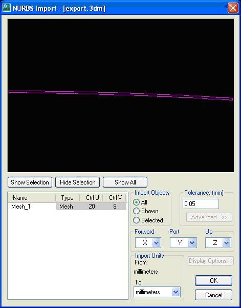
FILE IMPORT + PREPARATIONS BEFORE EXPANSION
1. Set Surface Properties:
a. Name required for templates only
b. correct Stock properties
c. correct Throw
d. Mode ‘Solid’’
e. Isolines ‘None’
f. colour conform stock
g. correct Markside
2. Create Cut Sections (settins as for Reference Lines in Structure)
3. Create Marklines, settings (Edit Labels):

4. Name at least the following Marklines: a. deck at side b. tankt at side 5. Split surfaces when they do not fit the stock
Note: do not toggle on the labels for the solids since they will appear also in the 3D solid model in the unit.
